Sunday, February 23, 2014

Unix file basics : Inode, Soft Vs Hard link, Device files, Named pipes

Inodes

Every file in a Linux/Unix operating system has an inode associated with it with an exception of Solaris ZFS, which does not have inodes. Inodes basically work very similar to an appendix of a book. Every Inode will have below information about the file.
1. owner
2. permissions
3. size
4. time of last access
5. creation time
6. group id
7. Pointers to data blocks associated with the file content
Note: Inode does not provide filename however.
File-Basics

File Types

There are basically 5 types of files in any unix operating system.
1. Regular
2. Directory
3. Symbolic links (hard link & soft link)
4. Device files (character special and block special device)
5. Named pipes
The Character in the first column of ls -l command identifies the type of a file.
# cd /
# ls -l bin
lrwxrwxrwx   1   root   root  9  Sep  19  15:41   bin -> ./usr/bin
-   Regular files
d   Directories
l   Symbolic links
b   Block-special device files
c   Character-special device files
p   Named pipes

Files and Directories

The regular files can store different types of data and can be easily created using touch command or vi editor. Directories hold the association between files and/or directories and inode numbers.
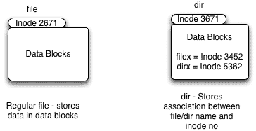
file directory and inodes

Soft links

As shown in the diagram soft links or symbolic links simply points to another file. It only contains the pathname of the file to which it is pointing
soft-link
1. Creation method
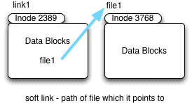
# touch file1
# ln -s file1 link1
# ls -l
-rw-r--r-- 1   root   root  0  Sep  19  14:41  link1
lrwxrwxrwx 1   root   root  5  Sep  19  15:41  link1 -> file1
2. The size of the soft link created in the example above is the no of characters in the pathname (file1), which is 5 (it can be absolute or relative).
3. If you delete the original file (file1) the soft link render as useless.
4. Soft links can reside on different file systems.

Hard links

Every file uses atleast one hard link. So when you create a new file a new directory entry is created which is called link count. So when you create a new hard link to this file the link count increaments by 1.
hard link
1. creation method
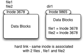
# touch file1
# ls -l
-rw-r--r-- 1  root  root  0  Sep  23  13:19  file1
# ln file1 file2
# ls -l
-rw-r--r--  2  root  root  0  Sep  23  13:19  file1
-rw-r--r--  2  root  root  0  Sep  23  13:19  file2
# ls -li
1282  -rw-r--r--  2  root  0  root  0  Sep  23  13:19  file1
1282  -rw-r--r--  2  root  0  root  0  Sep  23  13:19  file2
# find . -inum 1282
./file1
./file2
2. The link count increases by one, everytime you create a new hard link to the file as shown above.
3. Even if you delete any one of the file, it has no effect on the other file. Only the link count decrements
4. Hard links can not cross the file system.

Device files

In UNIX operating system any physical device has a file associated with it called as device file. It’s an interface that interacts with device drivers. Unlike other file types they do not hold any data in data blocks instead they use the inodes to store the major and minor no for any device file.
device file
# cd /dev/
# ls -l
crw-r-----  1  root  tty   4,  0  Sep  23  12:51  tty0
brw-rw----- 1  root  disk  8,  1  Sep  23  12:51  sda0
Major device no – Specific device driver required to access a device
minor device no – specific unit of the type that the device driver controls.
For example if you have 10 HP printers, the major no will be the HP printer devices driver and minor no would be the instance of printer (1,2 .. upto 10).
Device files are of 2 types
1. Character special
2. Block special
Character special Device files
1. Character “c” in the filrst column of ls -l command output identifies a character special device file
2. Data is accessed as data stream (character by character , 1 byte at a time)
3. Example : tty, serial, virtual terminals
# ls -l
crw-r-----  1  root  tty   4,  0  Sep  23  12:51  tty0
Block special Device file
1. Character “b” in the first column of ls -l command output identifies a character special device file
2. Data is accessed as defined block size for that device
3. Example : Hard Disk, CD/DVD
# ls -l
brw-rw-----  1  root  disk   8,  1  Sep  23  12:51  sda0

Named Pipes

- Named pipes are special files which are used for interprocessor communications. Unlike normal pipes you can read from and write to the named pipes. For this reason they are also called as FIFO (file in file out).
- mknod() or mkfifio() are common examples which make use of named pipes in order to access the pipe by name.
- As shown in the example below 2 processes (gzip and cat) can simultaneously access the Named pipe to write to and read data from it.
# mkfifo test_pipe
# gzip -9 -c > test_pipe < out.gz
# cat file1 > test_pipe
# ls -l test_pipe
prw-rw-----  1  root  root  0  Sep  23  12:51  test_pipe


Monday, February 17, 2014

Memory Mangement

Memory management units (MMUs) are incorporated in, or available for, a wide range of embedded CPUs. Under some circumstances their use is mandatory; in other situations they might represent an unwanted overhead. This article looks at what MMUs do and how they might be applied. Process and thread models for multi-tasking are compared and contrasted, and an intermediate option is considered that might provide a compromise between security and performance requirements.

Physical and logical addresses
When you first start learning how to program, the concept of an address is unimportant, as high level languages insulate the programmer from such nastiness. It is only when a developer wants to understand or write assembly language or really appreciate what is happening with pointers that addresses become a concern.

Every byte of memory has a unique address. Actually that is not quite true, as some processor architectures utilize multiple address spaces, but ultimately every byte may be specified uniquely in some way. Commonly, a system has a single area of memory with a starting address of zero. This is not a firm rule, as the memory architecture could be set up such that the address space starts at some other value. Other systems have multiple areas of memory that may not be contiguous – maybe the program and data memory are separate, for example.

Such addresses are physical addresses and are the values emitted by the CPU and systems immediately around it, and are decoded by the memory system. For many systems, physical addresses correspond directly to logical addresses, which are the ones used by software. In other systems, there is no such matching. A difference between a logical and physical address may occur for a number of reasons.

If a CPU has a paged memory architecture, the software may work with shorter (logical) addresses than would be needed to access the complete (physical) address space. Adjusting the “page” moves a window of addresses through the physical address space. For example, the original x86 architecture used 16-bit logical addresses (giving a 64K range) and 20-bit physical addresses (accessing up to 1M). Setting up the base register enabled the logical address space to be mapped onto a 64K area within the 1M space (on a 16-byte boundary).

Paged addressing is uncommon nowadays. More typically CPUs use 32-bit addresses to access a flat 4G address space. However, there may still be a non-correspondence between logical and physical addresses because a memory management unit (MMU) processes addresses emitted by the CPU. An MMU gives a lot of flexibility to remap physical memory to convenient logical addresses. It can also render parts of the physical address space inaccessible to software, which is a powerful protection mechanism.

Operating systems and multi-tasking
Most modern embedded systems are built using an operating system of some kind. This may be a simple multi-tasking kernel, or it may be a real-time operating system (RTOS) with a wide range of services, or it could be a “full” operating system like Linux. Broadly speaking, any kind of operating system supports a multi-tasking model, which may be “thread model” or “process model”; these two types are essentially characterized by their use or non-use of an MMU.

Multi-tasking – thread model
Most RTOS products on the market are thread model. This means that all the tasks’ (now called threads) code and data occupy the same address space, along with that of the RTOS itself, as illustrated in Figure 1.


Theoretically, but hopefully not in practice, one thread can access and/or corrupt the code and data of another thread or of the RTOS. Obviously, this possibility is only of passing interest if the code is properly debugged and from a trustworthy source. The big benefit of thread model is that the context switch is fast, as only the CPU registers need to be saved and restored.
Multi-tasking – process model
Higher end operating systems like Linux and Windows, along with a few RTOS products, use process model. By using the MMU, each task (now called a process) occupies its own private address space, starting at address 0, as illustrated in Figure 2. In effect, a process is given the impression that it has exclusive access to the entire machine.


Figure 2: Multitasking using a process model

This model has the great benefit that each process has no access to, or even awareness of, other processes’ memory or that of the OS itself. This permits the construction of more secure systems, where a badly behaved or seriously buggy process should have no effect on the rest of the system. The downside is that a context switch is significantly slower than with thread model, as apart from the save and restore of the CPU registers, the memory needs to be remapped using the MMU.

Thread protected mode
Some RTOS products offer an interesting compromise by making limited use of an MMU, while still using thread mode. This is commonly called “thread protected mode”. This facility is implemented such that, on a context switch, only memory which the current thread has authorization to access (i.e. its own along with any shared or specific RTOS memory areas) is rendered visible. This slightly increases the context switch time, as the MMU needs to be set up, but this is a lower overhead than a full remapping required for process model. Figure 3 shows a system where Task 2 is in control while Figure 4 illustrates the result of adjusting the MMU when Task 4 gains control.


Figure 3: Memory management using a thread protected mode with Task 2 in control


Figure 4: Memory management using a thread protected mode with Task 4 gaining control

Summary
Modern embedded CPUs commonly incorporate an MMU, or one may be available as an option. To use high-end operating systems like Linux, an MMU is essential. For most RTOS products, an MMU is not required, but in many cases it may be used to provide some additional security.